- 您现在的位置:买卖IC网 > Sheet目录1994 > DS2415P+T&R (Maxim Integrated Products)IC TIME CHIP 1-WIRE 6-TSOC

DS2415
14 of 14
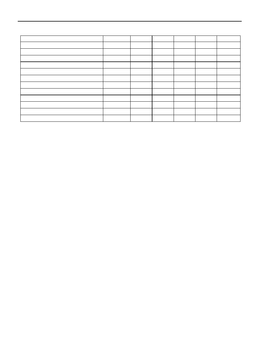
AC ELECTRICAL CHARACTERISTICS
(-40°C to +85°C, VPUP = 2.5V to 6.0V, VBAT = 2.5V to 5.5V)
PARAMETER
SYMBOL MIN
TYP
MAX
UNITS NOTES
Time Slot
tSLOT
60
120
ms
Write 1 Low Time
tLOW1
115
ms
14
Write 0 Low Time
tLOW0
60
120
ms
Read Low Time
tLOWR
115
ms
14
Read Data Valid
tRDV
15
ms
13
Release Time
tRELEASE
015
45
ms
Read Data Setup
tSU
1
ms
6
Recovery Time
tREC
1
ms
Reset Time High
tRSTH
480
ms
5
Reset Time Low
tRSTL
480
960
ms
8
Presence Detect High
tPDH
15
60
ms
Presence Detect Low
tPDL
60
240
ms
NOTES:
1. All voltages are referenced to ground.
2. Measured with outputs open.
3. VPUP = external pullup voltage.
4. Input load is to ground.
5. An additional reset or communication sequence cannot begin until the reset high time has expired.
6. Read data setup time refers to the time the bus master must pull the I/O line low to read a bit. Data is
guaranteed to be valid within 1
ms of this falling edge.
7. Under certain low voltage conditions VIL1MAX may have to be reduced to as much as 0.5V to always
guarantee a Presence Pulse.
8. The reset low time (tRSTL) should be restricted to a maximum of 960
ms, to allow interrupt signaling,
otherwise, it could mask or conceal interrupt pulses.
9. When VBAT ramps up, the oscillator is always off.
10. At VBAT = 3V
± 10%
11. At VBAT = 5V
± 10%
12. VIH1 has to be VBAT -0.3V or higher.
13. The optimal sampling point for the master is as close as possible to the end time of the 15s tRDV
period without exceeding tRDV. For the case of a Read-One Time Slot, this maximizes the amount of
time for the pull-up resistor to recover to a high level. For a Read-Zero Time Slot, it ensures that a
read will occur before the fastest 1-Wire device(s) release the line.
14. The duration of the low pulse sent by the master should be a minimum of 1s with a maximum value
as short as possible to allow time for the pull-up resistor to recover the line to a high level before the
1-Wire device samples in the case of a Write-One Time or before the master samples in the case of a
Read-One Time.
发布紧急采购,3分钟左右您将得到回复。
相关PDF资料
DS2417X/T&R
IC TIMECHIP W/INTRPT 1WIRE CSP
DS26502LN+
IC T1/E1/J1 64KCC ELEMENT 64LQFP
DS26503LN+
IC T1/E1/J1 BITS ELEMENT 64-LQFP
DS3105LN+
IC TIMING LINE CARD 64-LQFP
DS3106LN+
IC TIMING LINE CARD 64-LQFP
DS3231MZ+
IC RTC I2C 8SOIC
DS3231SN#T&R
IC RTC W/TCXO 16-SOIC
DS3232MZ+
IC RTC W/SRAM I2C 8SOIC
相关代理商/技术参数
DS2415P-001-711
功能描述:实时时钟
RoHS:否 制造商:Microchip Technology 功能:Clock, Calendar. Alarm RTC 总线接口:I2C 日期格式:DW:DM:M:Y 时间格式:HH:MM:SS RTC 存储容量:64 B 电源电压-最大:5.5 V 电源电压-最小:1.8 V 最大工作温度:+ 85 C 最小工作温度: 安装风格:Through Hole 封装 / 箱体:PDIP-8 封装:Tube
DS2415P-001-711/T&R
功能描述:实时时钟
RoHS:否 制造商:Microchip Technology 功能:Clock, Calendar. Alarm RTC 总线接口:I2C 日期格式:DW:DM:M:Y 时间格式:HH:MM:SS RTC 存储容量:64 B 电源电压-最大:5.5 V 电源电压-最小:1.8 V 最大工作温度:+ 85 C 最小工作温度: 安装风格:Through Hole 封装 / 箱体:PDIP-8 封装:Tube
DS2415P-001-721
功能描述:实时时钟 RoHS:否 制造商:Microchip Technology 功能:Clock, Calendar. Alarm RTC 总线接口:I2C 日期格式:DW:DM:M:Y 时间格式:HH:MM:SS RTC 存储容量:64 B 电源电压-最大:5.5 V 电源电压-最小:1.8 V 最大工作温度:+ 85 C 最小工作温度: 安装风格:Through Hole 封装 / 箱体:PDIP-8 封装:Tube
DS2415P-001-721/T&R
功能描述:实时时钟 RoHS:否 制造商:Microchip Technology 功能:Clock, Calendar. Alarm RTC 总线接口:I2C 日期格式:DW:DM:M:Y 时间格式:HH:MM:SS RTC 存储容量:64 B 电源电压-最大:5.5 V 电源电压-最小:1.8 V 最大工作温度:+ 85 C 最小工作温度: 安装风格:Through Hole 封装 / 箱体:PDIP-8 封装:Tube
DS2415P-W
功能描述:实时时钟 RoHS:否 制造商:Microchip Technology 功能:Clock, Calendar. Alarm RTC 总线接口:I2C 日期格式:DW:DM:M:Y 时间格式:HH:MM:SS RTC 存储容量:64 B 电源电压-最大:5.5 V 电源电压-最小:1.8 V 最大工作温度:+ 85 C 最小工作温度: 安装风格:Through Hole 封装 / 箱体:PDIP-8 封装:Tube
DS2415V
制造商:DALLAS 制造商全称:Dallas Semiconductor 功能描述:1-Wire Time Chip
DS2415X
功能描述:IC TIME CHIP 1-WIRE CSP RoHS:否 类别:集成电路 (IC) >> 时钟/计时 - 实时时钟 系列:- 产品培训模块:Obsolescence Mitigation Program 标准包装:1 系列:- 类型:时钟/日历 特点:警报器,闰年,SRAM 存储容量:- 时间格式:HH:MM:SS(12/24 小时) 数据格式:YY-MM-DD-dd 接口:SPI 电源电压:2 V ~ 5.5 V 电压 - 电源,电池:- 工作温度:-40°C ~ 85°C 安装类型:表面贴装 封装/外壳:8-WDFN 裸露焊盘 供应商设备封装:8-TDFN EP 包装:管件
DS2416FP00K
制造商:Thomas & Betts 功能描述:200A,CON,3P4W,MG,416,3P208V,CC